


Interfacing IR Sensor With STM32 Discovery Board
STM32 Boards have 23 interrupt sources. In this article, we will see how STM32 handles interrupts at a primitive level.

Components Required:
- STM32F407 Discovery Board
- Infrared Sensor
- LEDs
- Breadboard
- Jumpers
- USB type A to Mini B Cable.
- Interfacing Diagram:
The following picture depicts the interfacing between the IR module and STM32 DISC Board. PA1 pin introduces interrupt as IR sensor detects an obstacle. The LED connected at PD1 indicates the interrupt status.
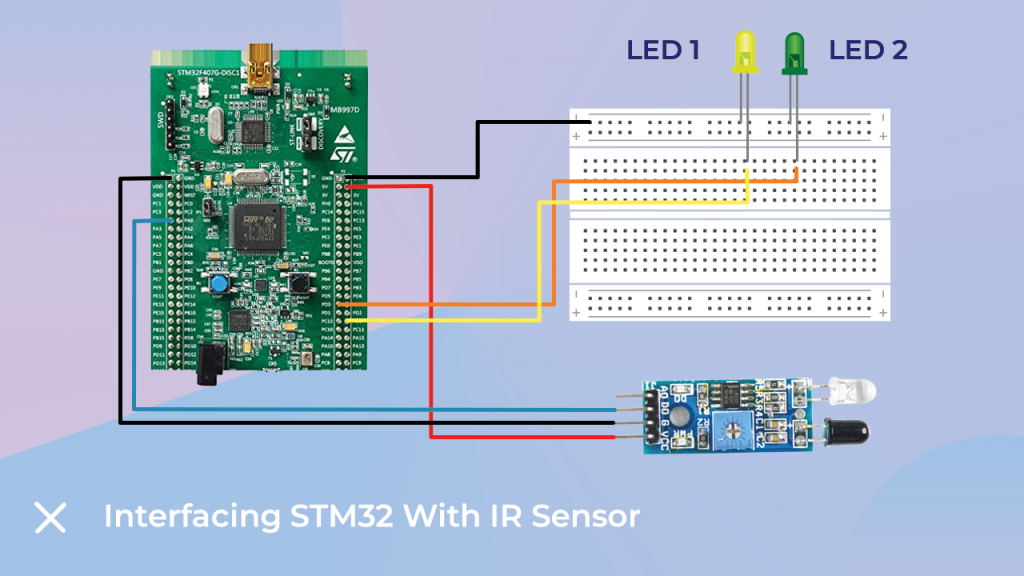
Pinout:
- LED1- PD0 (Pin 0 of Port D)
- LED2- PD1 (Pin 1 of Port D)
- IR (5V)- 5V of STM Board
- IR (Gnd)- GND of STM
- IR (Dout)- PA1 (Pin 1 of Port A)
Software:
Let’s move towards code writing and deployment. I have used for the programming of the board. The initial steps are software installing and selecting the board. After that, go to Files–>New Project–>C project and the perspective of the new project will open, as you can see in the following image.
- Step 1: Create New Project.
- Step 2: Write Code.
- Step 3: Save.
- Step 4: Build Project.
- Step 5: Debug.