How to Interface MPU6050 with the Arduino
In this blog, we will learn about the MPU6050 sensor. It calculates the angle and motion values of the accelerometer and the gyroscope. With this, we will also see its wide application range.

Introduction
Have you ever wonder how your mobile screen adjusts automatically in a frame when you move your smartphone vertically or horizontally? We can achieve this task with the help of IMU(Inertial Measurement Unit) MPU6050. In this tutorial, we will talk about MPU6050 and its interfacing with Arduino. MPU6050 has been developed by InvenSense company. It is designed for obtaining values of accelerometer and gyroscope.

What is MPU6050?
MPU6050 is an IMU device that stands for Inertial Measurement Unit. It is a six-axis motion tracking device that calculates a three-axis accelerometer and three-axis gyroscope data. The biggest advantage of this board it comes with a digital motion processor. The significance of DMP(Digital motion processor) is, it performs very complex calculations/operations from its side, thus freeing up the microcontroller’s work. It provides motion data like roll, pitch, yaw, angles, landscape, and portrait sense, Etc.
It is very precise while converting analog data into digital data bits because it has 16 bits assigned for each channel. Digital Motion Processor or the DMP(Digital Matrix Processor) is an embedded processor that can reduce the host processor’s computational load by acquiring and processing data from Accelerometer, Gyroscope, and an external Magnetometer.
We will look towards some of its main features like:
- 3- axis gyroscope
- 3- axis accelerometer
- 16-bit ADC conversion for each channel
- 1024 bit FIFO buffer
- Digital output temperature sensor
- Integrated Digital Motion Processor
- Inbuilt temperature sensor
Pinout

- VCC: This pin is used to provide power(5v /3.3v)
- GND: As usual for providing 0v
- SDA: This pin is used for obtaining data serially from the sensor
- SCL: This pin is used for serial clock input
- XDA: This is used as an SDA for configuring and reading from an external sensor(Optional)
- XCL: This is used as an SCL for configuring and reading from external sensor (Optional)
- AD0: This is I2c slave address Bus, (least significant bit)
- INT: This one is an Interrupt pin for an indication of data ready
How does it Work?
How does the Accelerometer work?
An accelerometer works on the principle of the piezoelectric effect. Consider a cuboidal box with a ball inside it. If we move or tilt the box ball inside the box, it will fall on the box’s walls because of gravity. Similarly, IMU like MPU6050 also contains such MEMS (micro-electromechanical systems), which exactly work just like the cuboidal box with a ball inside it.
When the device/box is tilted, a ball inside the box falls upon the piezoelectric walls. Also, the analog data is captured from that wall’s channel and proceeds into digital data. It is often how an accelerometer works, and its output is so precise because it has 16-bit ADC present for every channel.
How does the Gyroscope work?
It works on the principle of Coriolis acceleration. Imagine that there’s a fork-like structure that’s in an exceedingly constant back-and-forth motion. Whenever you try to tilt this arrangement, the crystals experience a force within the direction of inclination. It often causes a result of the inertia of the moving fork. The crystals thus produce a current in consensus with the piezo effect, and the current is amplified.
Interfacing with the Arduino
As MPU6050 is an I2C communication device, the connections with the Arduino are pretty simple. The following circuit diagram will show you how the connections are made with Arduino.

Connections of MPU6050 with Arduino is as follows:
| Arduino | MPU6050 |
|---|---|
| 5v/3v | VCC |
| GND | GND |
| A5/ SCL pin | SCL |
| A4/SDA pin | SDA |
| pin 2 | INT |
Programming
To obtain the data from MPU6050, you will need to install the wire.h library.
You can download both the libraries from the following link:
From this code, we will get three basic parameters called Roll, Pitch, Yaw. Basically, what do these three things mean? When you are going through a car, you can measure its motion as forward, backward, left, and right. But, it will not be considered the same scenario when it comes to drones or flying vehicles. Flying control boards have different terminologies like yaw, pitch, and Rolls.
- The axis that runs front to the back of the drone is called the roll axis. The rotation around this axis is called roll motion.
- The axis that runs left to the right of the drone is called the pitch axis. The rotation around this axis is called pitch motion.
- The axis that runs top to the bottom of the drone is called the yaw axis. The rotation around this axis is called the yaw motion.
In the short words, we can say that,
- Rotation around the front-to-back axis is called roll.
- Rotation around the side-to-side axis is called pitch.
- Rotation around the vertical axis is called yaw.
For explaining the things, I will show you an image for a better understanding.

Output

From the above code, we have successfully got the Data Roll/ pitch/ Yaw.
Roll, pitch, yaw are the manipulated data obtained by gyroscopic angles of MPU6050. If you want to calculate basic accelerometer and gyroscopic values, you can receive them in some steps. For that, first, you have to install the library

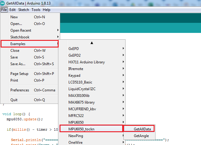
Browse the library from its path directory. It is the process of adding the library to MPU6050. After including the library to Arduino IDE, you can select the code from the path.
Once the MPU-6050 library is added to Arduino IDE, we have a list of examples to choose from, like
- GetAllData
- GetAngle

#include <MPU6050_tockn.h>
#include <Wire.h>

MPU6050 mpu6050(Wire);

long timer = 0;

void setup() {
  Serial.begin(9600);
  Wire.begin();
  mpu6050.begin();
  mpu6050.calcGyroOffsets(true);
}

void loop() {
  mpu6050.update();

  if(millis() - timer > 1000){

    Serial.println("=======================================================");
    Serial.print("temp : ");Serial.println(mpu6050.getTemp());
    Serial.print("accX : ");Serial.print(mpu6050.getAccX());
    Serial.print("\taccY : ");Serial.print(mpu6050.getAccY());
    Serial.print("\taccZ : ");Serial.println(mpu6050.getAccZ());

    Serial.print("gyroX : ");Serial.print(mpu6050.getGyroX());
    Serial.print("\tgyroY : ");Serial.print(mpu6050.getGyroY());
    Serial.print("\tgyroZ : ");Serial.println(mpu6050.getGyroZ());

    Serial.print("accAngleX : ");Serial.print(mpu6050.getAccAngleX());
    Serial.print("\taccAngleY : ");Serial.println(mpu6050.getAccAngleY());

    Serial.print("gyroAngleX : ");Serial.print(mpu6050.getGyroAngleX());
    Serial.print("\tgyroAngleY : ");Serial.print(mpu6050.getGyroAngleY());
    Serial.print("\tgyroAngleZ : ");Serial.println(mpu6050.getGyroAngleZ());

    Serial.print("angleX : ");Serial.print(mpu6050.getAngleX());
    Serial.print("\tangleY : ");Serial.print(mpu6050.getAngleY());
    Serial.print("\tangleZ : ");Serial.println(mpu6050.getAngleZ());
    Serial.println("=======================================================\n");
    timer = millis();

  }

}
Uploading this code into Arduino the MPU6050 will give you the values. You can see the output in the following image:
Output for Accelerometer and Gyroscope

Applications
Here are some applications of the MPU6050 sensor:
- 3D remoter controller
- In 3D mice controller
- In wearable health-tracking, fitness-tracking devices
- In drones and quadcopters, MPU6050 is used for position control.
- Used in controlling Robotic Arm
- Hand gesture control devices
- In Self-balancing robot
- In Humanoid robot for tilt, rotation, and balancing
- In smartphones for adjusting the frame
- Used in gimbals system for stabilization on drones

Final Words
In this tutorial, it has been concluded that the MPU6050 chip is a highly applicable device in many systems. It is used in wide applications and is considered the most crucial parameter of the system. Without this sensor, we can not make most of the complicated processes in robotics and the embedded fields. If you have any queries related to any doubt, you can drop them in the comment section.


