


Temperature Controlled Fan using Arduino – Step by Step Guide with Code
In this step by step guide we will show you how to make a temperature-controlled fan using Arduino.
Hey guys! hope you are doing well? In this blog, we will be showing a step by step guide on how to make a temperature-controlled fan using Arduino. Which can be very useful in many places. Let’s hop into it and see what this blog is about.
Introduction
Temperature controlling is required in many places such as server rooms, houses, industries, etc. So this project can be very useful in understanding the basics, how you can control the temperature at your home. You can take this as a DIY project which can be used anywhere. Here the Temperature controlled fan will act to the temperature changes.
We have also written a blog on what , if you are interested feel free to read that as well to understand more about these types of sensors.
We are going to do this with a DHT11 temperature and humidity sensor. It can be done in various other ways as well. With a thermistor or other sensors like a contactless temperature sensor. But thermistor usually needs contact of the surface and contactless sensors can be costly. While DHT11 is a cost-effective sensor.
In this article, we are going to discuss making a temperature-controlled fan using Arduino. With this circuit, we will be able to change the fan speed in our home or any place according to the room temperature and also display the temperature and fan speed changes on a 16×2 LCD display. To do this we will be using an Arduino UNO Board, LCD, DHT11 sensor Module, and DC fan. Let’s get started.
How does it Work?
This project works in three parts –
In the first step, the sensor senses the temperature by temperature and humidity sensor namely DHT11.
In the second step, the sensor’s output is taken and conversion of temperature value into a suitable number in Celsius scale is done. The fan speed is controlled by using PWM signals. And last part of the system shows humidity and temperature on LCD and Fan runs.
Then we have programmed our Arduino according to the requirements. Working on this is very simple. We have generated PWM from Arduino and put it at the base terminal of the transistor. Then transistor generates voltage with respect to the PWM input.
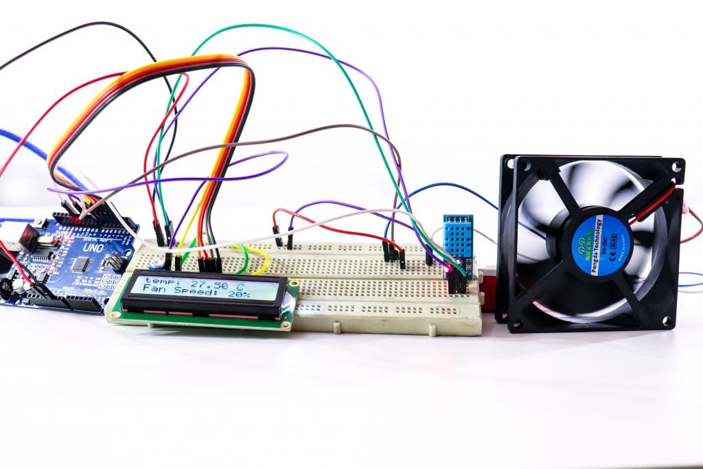
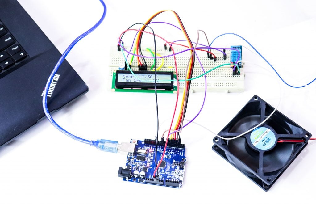
Connections
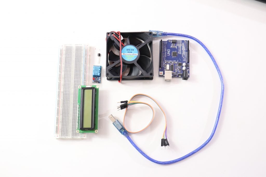
Below are the components that we require to perform this project. Most of the components are easily available on our website.
Step 1 : Gather all these components
Step 2 : LCD connection with Arduino
LCD is directly connected to Arduino (Check this tutorial for more details: . Connect pins of LCD- RS, EN, D4, D5, D6, and D7 to Arduino’s digital pin numbers 7, 6, 5, 4, 3, and 2.
Step 3 : DHT 11 temperature and humidity sensor connection
And a DHT11 sensor module is also connected to digital pin 12 of Arduino. Digital pin 9 is used for controlling fan speed through the transistor.
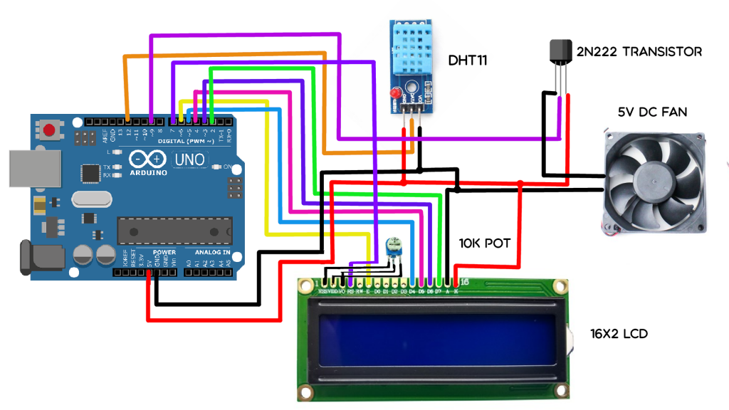
1.2 Circuit Diagram
Step 4: Upload the code
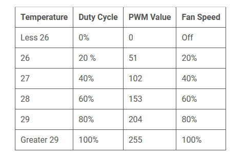
The below section is for the code. Here the first table gives you an idea of what PWM value will be the speed of the fan. You can change values according to your need.
Code
Before writing the code, please refer to the below table.
Final words
In this article, we learned about, how we can make a temperature-controlled fan circuit. Using an Arduino, DHT11, and few other components. Which can be used pretty much any place where temperature needs to be maintained at specific levels. Like in some industries, houses, etc. We checked how it actually works and we also learned how to code for a temperature-controlled fan. If you have any feedback, feel free to review it.