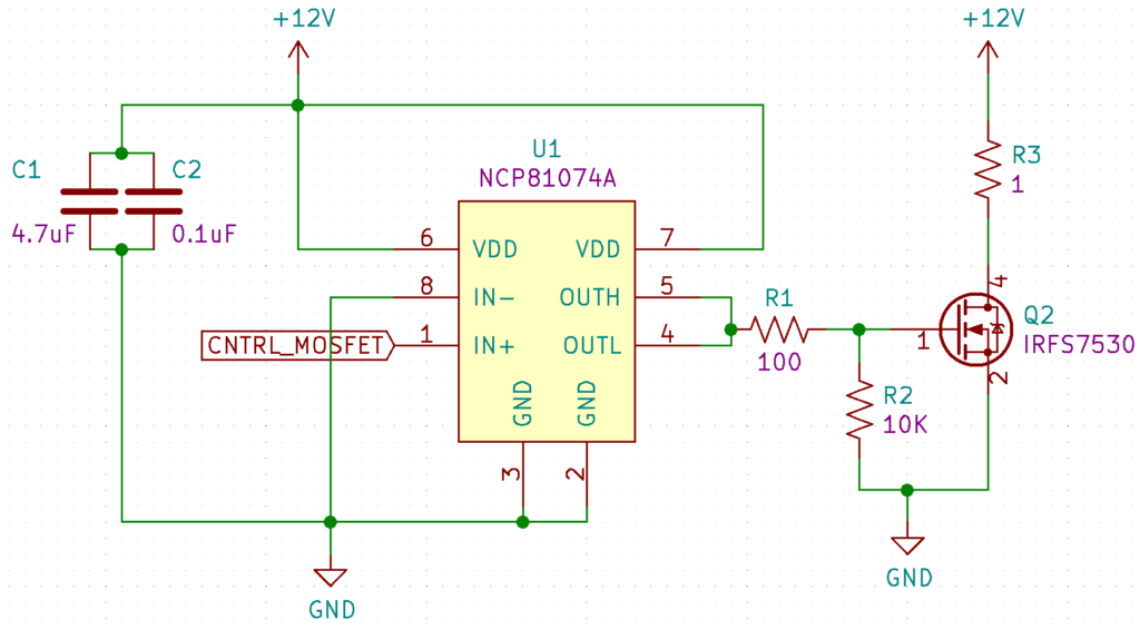
MOSFET Gate Protection Circuits: A Simple Guide for Electronics Enthusiasts

When working with MOSFETs (Metal-Oxide-Semiconductor Field-Effect Transistors) in your electronics projects, one common issue is gate voltage damage. MOSFETs are sensitive components, and if their gate is exposed to high voltages or static discharge, it can easily burn out. Thankfully, you can protect your MOSFET gate using a simple protection circuit.
The Problem :
In many circuits, especially those used for switching and amplification, the gate of the MOSFET is driven by a microcontroller or another low-voltage signal. If a spike or surge in voltage occurs, the gate may receive more than it can handle. This can lead to permanent damage to the MOSFET and cause your circuit to fail.
The Solution :
To protect the gate, a simple gate protection circuit can be used, typically consisting of a Zener diode and a resistor. The Zener diode will clamp any excess voltage and prevent it from exceeding a safe threshold. The resistor limits the current, ensuring that the MOSFET is not exposed to damaging conditions.
Practical Example :
Let’s say you’re controlling a MOSFET with a 5V signal from a microcontroller. To prevent accidental voltage spikes from damaging the gate, you could place a 4.7V Zener diode in parallel with the gate, and a 1kΩ resistor in series. This combination ensures that even if there’s a spike, the voltage at the gate stays safe.
Sample Calculation :
If the Zener diode is rated for 4.7V and the input voltage is 5V, the current through the resistor would be:
I=R(Vin−VZener)=1000Ω(5V−4.7V)=0.0003A(300μA)
This is a very small current, which won’t damage the MOSFET or the Zener diode.
Product Recommendation :
Looking for reliable protection components for your next project? Check out MOSFETs and Zener diodes, all Made in India, at SmartXProKits.
Shop now at SmartXProKits.in and support India’s innovative electronics scene!


