


Interfacing Hall Effect Sensor with Arduino – Connection Code
In this article, we will discuss the Hall Effect sensor working principle, interfacing with Arduino, and code.
Hall Effect sensor works on the principle of magnetic field measurement.
Hall Effect shows the behavior of charge carriers when it is exposed to electricity and magnetic fields. This principle can be explained as an extension to Lorentz Force. The sensors working on this concept are called Hall Effect Sensors. These Hall Effect Sensors are in high demand and have very wide applications such as Wheel speed sensors, Switches, Positional sensors, & more.
Hall Effect Sensors are components that the external magnetic field can activate.
How does Hall Effect Sensor Work?
An external force field activates them. We all know that a field of force has two important characteristics flux (B) and polarity (North and South Poles). The output from a Hall effect sensor is that the function of field density around the device. When magnetic density around the sensor increases a certain threshold, the sensor detects and generates an output voltage called the Hall Voltage, VH.
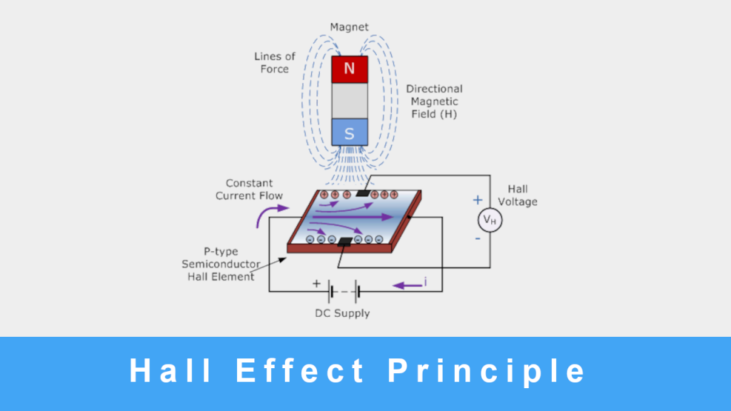
Hall Effect Sensors consist basically of a thin piece of rectangular semiconductor unit material like gallium arsenide (GaAs), indium antimonide (InSb), or indium arsenide (InAs), passing a constant current through itself. When the device is kept within a magnetic flux, the magnetic flux lines provide a force on the semiconductor material, which diverts the charge carriers, electrons, and holes to either side of the semiconductor slab. This movement of charge carriers could result from the magnetism they experience passing through the semiconductor material.
As electrons and holes move sidewards, a potential difference is generated between the two sides of the semiconductor material by the build-up of these charge carriers. Then, the movement of electrons through the semiconductor material is affected by the presence of an external magnetic field at right angles. This effect is greater in flat rectangular-shaped material.
The effect of creating a significant voltage by using a magnetic field is called the Hall Effect. For creating a potential difference across the device, the magnetic flux lines must be perpendicular (90o) to the flow of current and be of the correct polarity, generally a south pole.
The Hall effect provides data about the type of magnetic pole and magnitude of the magnetic field. For example, a south pole would cause the device to produce a voltage output, while a north pole would not have affected it. Generally, Hall Effect sensors and switches are designed to be in the “OFF” (open circuit condition) when there is no magnetic field present. They only turn “ON” (closed-circuit condition) when subjected to a magnetic field of sufficient strength and polarity.
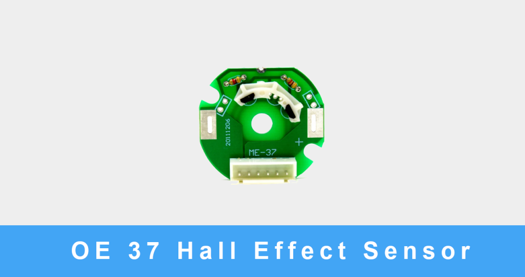
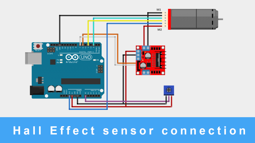
Interfacing Hall Effect sensor with Arduino
Once you are ready with your Hardware and Code, upload the code to the Arduino. I have used a 9V battery to power the whole setup. You can use any preferable power source. Now connect the sensor to the motor, as shown in the below GIF.
After mounting the sensor properly on the motor, connect the sensor wires to the Arduino, as shown in the below image. We are using here an l298n driver as shown in the below connection diagram.
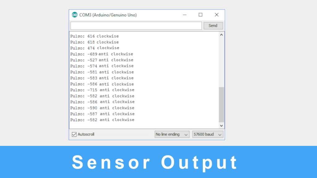
Once the connection is set up, you can upload the below code.
Code
//Program: Motor DC com encoder const byte Encoder_C1 = 2; const byte Encoder_C2 = 4; byte Encoder_C1Last; int duration; boolean direction; //Pins of driver H L298N #define pino_motor1 6 #define pino_motor2 7 void setup() { Serial.begin(57600); //Pin potentiometer pinMode(A0, INPUT); //Defining pins pinMode(pino_motor1, OUTPUT); pinMode(pino_motor2, OUTPUT); EncoderInit(); } void loop() { Serial.print(“Pulso: “); Serial.print(duration); int valor = analogRead(A0); if (valor >= 512) { digitalWrite(pino_motor1, LOW); digitalWrite(pino_motor2, LOW); //delay(1000); digitalWrite(pino_motor1, LOW); digitalWrite(pino_motor2, HIGH); Serial.println(“anti clockwise”); } else { digitalWrite(pino_motor1, HIGH); digitalWrite(pino_motor2, LOW); Serial.println(“clockwise”); } duration = 0; delay(100); } void EncoderInit() { pinMode(Encoder_C2, INPUT); attachInterrupt(0, calculapulso, CHANGE); } void calculapulso() { int Lstate = digitalRead(Encoder_C1); if ((Encoder_C1Last == LOW) && Lstate == HIGH) { int val = digitalRead(Encoder_C2); if (val == LOW && direction) { direction = false; //Reverse } else if (val == HIGH && !direction) { direction = true; //Forward } } Encoder_C1Last = Lstate; if (!direction) duration++; else duration–; }
Final Words
Here, we learn about how the hall sensor works and how to make its connection with Arduino. I hope you learn something from the Arduino hall effect sensor article and enjoyed building something new. Until next time.