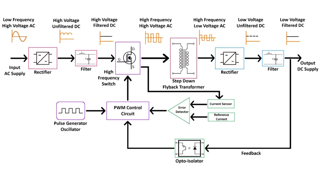
SMPS High-Frequency Design Guide – Beat the Noise!

Switch Mode Power Supplies (SMPS) operate at high frequencies to boost efficiency and reduce transformer size. But if not designed right, these frequencies create EMI (electromagnetic interference), signal distortion, and heating issues.
🛠️ The Problem: High Frequency = High Risk
In high-frequency SMPS circuits (typically 50kHz–500kHz), poor PCB layout, wrong component placement, or undersized inductors can cause noisy outputs and poor performance. This is critical in IoT, lighting, or embedded systems.
🔧 The Fix: Use Proper Layout & Fast Components
Minimize loop area between switching devices and capacitors.
Use low ESR capacitors and fast-switching MOSFETs.
Keep signal and power grounds separate, joining them at one point.
💡 Real-Life Example
An Indian prototyper building a smart charger noticed high ripple on the 5V rail. After switching to a faster MOSFET (like IRF540N) and reducing the layout loop, ripple dropped by 60%.
🔢 Sample Calculation
To size your inductor for 100kHz at 12V output and 1A current:
Use L = (Vout × (1 – D)) / (f × ΔI)
Assume D = 0.5, ΔI = 0.3A →
L = (12 × 0.5)/(100kHz × 0.3) = 200µH
🛒 Made in India Products for SMPS Success
🔧 Flux Paste for neat assembly
Shop now at SmartXProKits.in
🇮🇳 Support our work and India’s innovation—buy from our Make in India site!


