


RFID and Password Based Door Lock System Using Arduino
A step by step guide for RFID and Password based door lock system using Arduino
Generally, the Basic requirement of security can be done by using mechanical electric door locks. Now, in this digital world, we are using various digital technology. For example, identification of digital device using cards or token, door lock system using digital technology, automatic door opening and closing etc. Nowadays, in most hotels, you can see RFID Door Lock Mechanism where you don’t need a key to unlock the room. This kind of systems used for controlling the movement of a door without using a key. This article represents the RFID and Password based Door Lock system.
Working Of Door Lock System
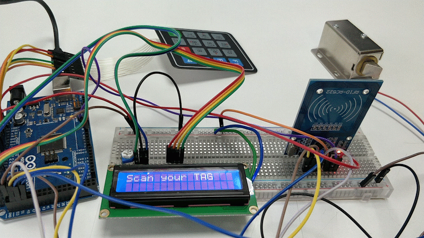
The RFID reader communicates with the Arduino through the SPI protocol and different Arduino boards have different SPI pins. Here, we are using RFID Reader/Writer RC522 SPI S50 with RFID Card.
- After, doing all the connection properly and upload the code. It will ask for scanning the card/tag and ask for the set password.
- On scanning the wrong tag or on entering the wrong password, it will show the message of wrong input.
- On scanning the right tag and entering the right password, it will send us a confirmation message that the door has opened.
Pin Connection of the components with Arduino
1. Connection of RFID reader with Arduino Mega

Connect the MFRC522 module with the Arduino Mega as per the below pin connections. Different Arduino’s have different SPI pins. If you are using different Arduino, then make connections according to that.
RC522 Reader- Uno/Nano- MEGA
- SDA- D10- D9
- SCK – D13- D52
- MOSI- D11- D51
- MISO- D12- D50
- IRQ- N/A- N/A
- GND- GND- GND
- RST- D9- D8
- 3.3V- 3.3V- 3.3V
2. Connection of LCD with Arduino Mega
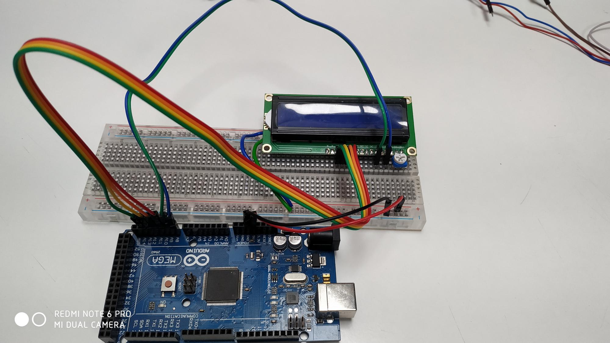
We are interfacing the LCD1602 with Arduino using the data pins of the LCD module. The same connection and circuit will work for all Arduino and compatible boards. Connect the circuit as per the below connection,
- VSS (0V)- Ground potential- Gnd
- VDD (5V)- Positive Voltage
- V0 (Contrast)- Contrast adjustment (used 10K pot)
- RS- Register select (Instruction select-0 and Data select-1)-
- R/W- Read/write (Read-0 and Write-1)-
- E- Enable pin
- D4- A10
- D5- A11
- D6- A12
- D7- A13
- LCD +A- 5V
- LCD-K- Gnd
3. Connection of Keypad of Arduino Mega
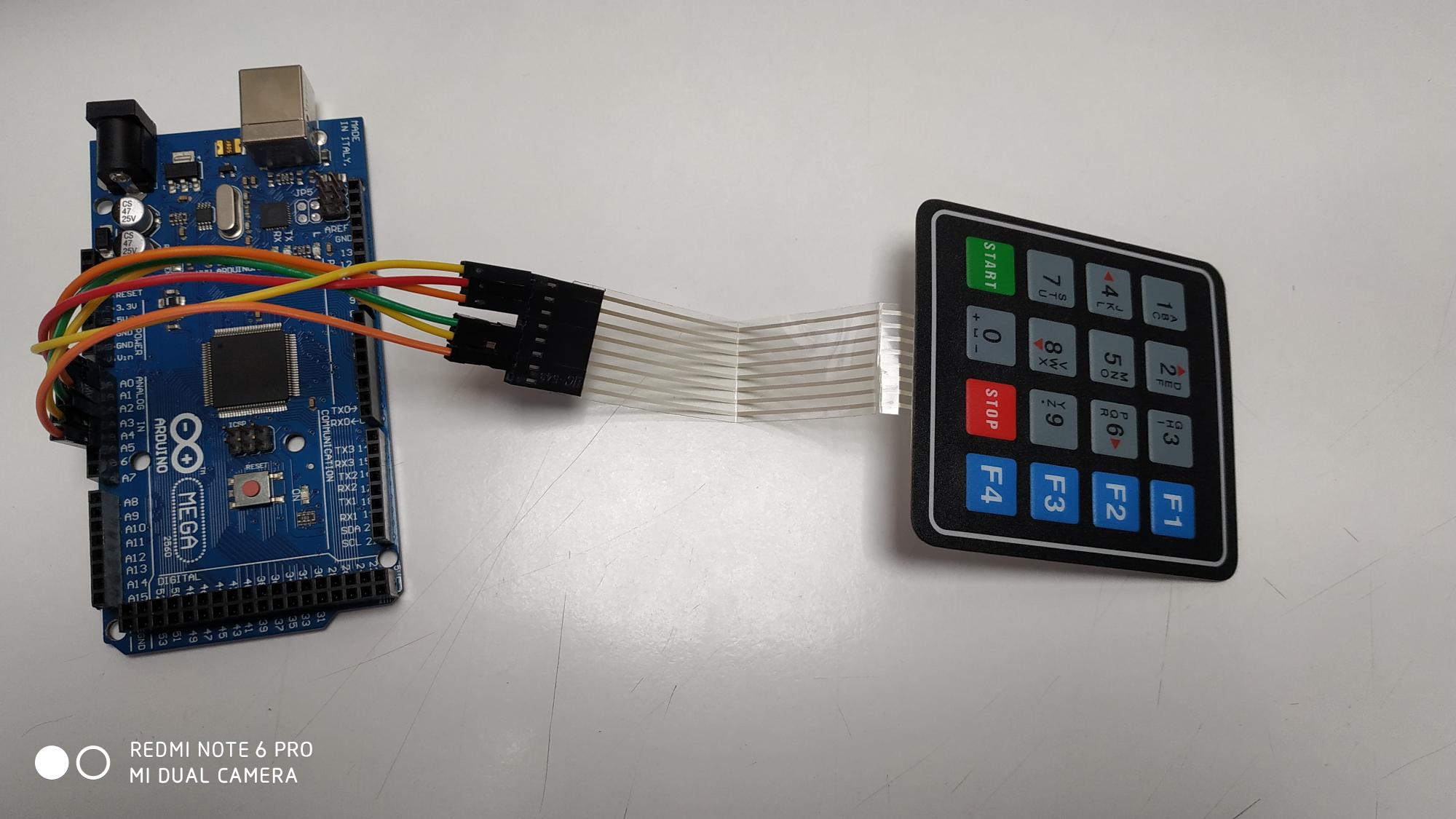
The 4X4 keypad has 8 connections but we don’t require the last column and row of the keypad. We only require 3X3 keypad for the password. So we won’t use the PIN 4 and 8 of the keypad. You can also use 4X3 keypad instead of 4X4 and 3X3 keypad.
- 1st pin- A0
- 2nd pin- A1
- 3rd pin- A2
- 5th pin- A3
- 6th pin- A4
- 7th pin- A5
4. Connection of Relay and Door lock solenoid with Arduino Mega
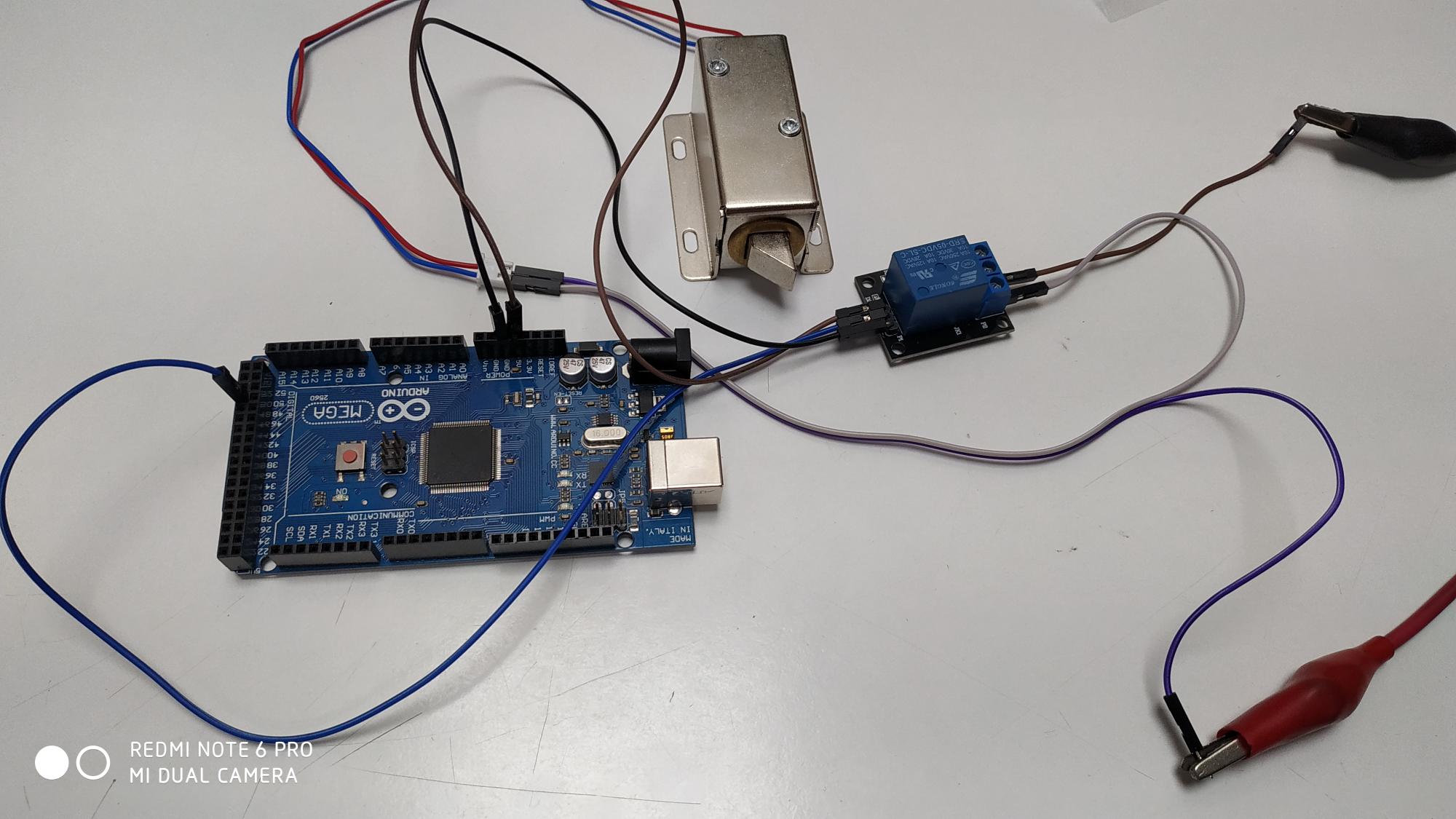
Here, we are using a 5V relay module. It has 3 inputs and they are,
- Vcc-Vcc
- Gnd- Gnd
- Signal- 49 (Active High)
And connect the 12V Door lock solenoid to the output of the relay module.
Scanning of your tag:
Enter the correct passward, Door will be opened.

Hope this tutorial helps you to learn about the RFID and Password based Door Lock system. You can easily make the security for your home with the reference of this tutorial so let’s hurry up!