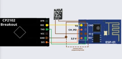
Programming ESP boards with the Arduino IDE can be straightforward and beginner-friendly. ESP boards, such as the popular ESP8266 and ESP32, are widely used in the Internet of Things (IoT) and DIY electronics projects. To get started, follow this beginner’s guide:
Step 1: Install the Arduino IDE
If you haven’t installed the Arduino IDE yet, you can download it for free from the official website: https://www.arduino.cc/en/software
Step 2: Install ESP board support
By default, the Arduino IDE doesn’t support ESP boards. To add support for ESP8266 and ESP32, you need to install additional board packages. Here’s how to do it:
For ESP8266:
- Open the Arduino IDE.
- Go to “File” > “Preferences”.
- In the “Additional Boards Manager URLs” field, enter the following URL and click “OK”:http://arduino.esp8266.com/stable/package_esp8266com_index.json
- Go to “Tools” > “Board” > “Boards Manager”.
- Search for “esp8266” and click “Install” to add support for the ESP8266 boards.
For ESP32:
- Open the Arduino IDE.
- Go to “File” > “Preferences”.
- In the “Additional Boards Manager URLs” field, enter the following URL and click “OK”: https://dl.espressif.com/dl/package_esp32_index.json
- Go to “Tools” > “Board” > “Boards Manager”.
- Search for “esp32” and click “Install” to add support for the ESP32 boards.
Step 3: Select the board
Now that you have installed the board packages, you can select your specific ESP board:
- Connect your ESP board to your computer via USB.
- Open the Arduino IDE.
- Go to “Tools” > “Board” and choose the appropriate ESP board from the list (e.g., “NodeMCU0 (ESP-12E Module)” for ESP8266 or “ESP32 Dev Module” for ESP32).
Step 4: Install the USB Driver (if necessary)
For some ESP boards, you might need to install a specific USB driver for your computer to recognize the board. Check the manufacturer’s website or product documentation for driver information.
Step 5: Upload your first sketch
Now you’re ready to upload your first sketch (program) to the ESP board:
- In the Arduino IDE, go to “File” > “Examples” > “01.Basics” > “Blink” to open the Blink example sketch.
- Verify that the correct board and port are selected in the “Tools” menu.
- Click the “Upload” button (right-arrow icon) to compile and upload the sketch to your ESP board.
- After a few moments, you should see the onboard LED (connected to pin 13 on most boards) blinking.
Congratulations! You’ve successfully uploaded your first sketch to the ESP board. Now you can explore more examples and start building your projects.
Remember to refer to the official documentation of the specific ESP board you are using for more detailed information and pin configurations. Happy tinkering!
Written by kanchan kan
- Industrial Automation141141 products
- Cooling Fan44 products
- Indicators1111 products
- Plastic Casing66 products
- Sensor2323 products
- Sleeve and cables55 products
- SMPS88 products
- Solid State Relay Module22 products
- Switches1818 products
- Temprature Sensor11 product
- 3D Printing189189 products
- 3D printing118118 products
- Combination Kit4747 products
- Electronic743743 products
- Audio55 products
- Battery/Charger Accessories2828 products
- Capacitors6464 products
- Connector4646 products
- cooling fan11 product
- Diode3535 products
- Displays1212 products
- IC and Chips6565 products
- IOT and Wireless99 products
- Leds2424 products
- Microcontrollers55 products
- Modules/Shield7575 products
- MOSFET / IGBT1414 products
- Power Supply2525 products
- Resistors130130 products
- Sensors5959 products
- SMD2828 products
- Switches1414 products
- Transistors6868 products
- Wire and Cables1212 products
- Hardware3232 products
- Hand Tools1414 products
- Hardware Accessories1414 products
- Printing22 products
- RC Plane and Drone99 products
- Robotic147147 products
- BO Motors1313 products
- General Purpose DC Motors2929 products
- Motor Drivers88 products
- Robotic Wheels & Tyres1414 products
- Servo Motor2727 products
- Stepper Motors88 products
- Synchronous Motor11 product
- Science Fair Project7070 products
- Final Year Ready Project Kit11 product
- STEM KIT2222 products
- E Books88 products


Leave a Reply
You must be logged in to post a comment.