


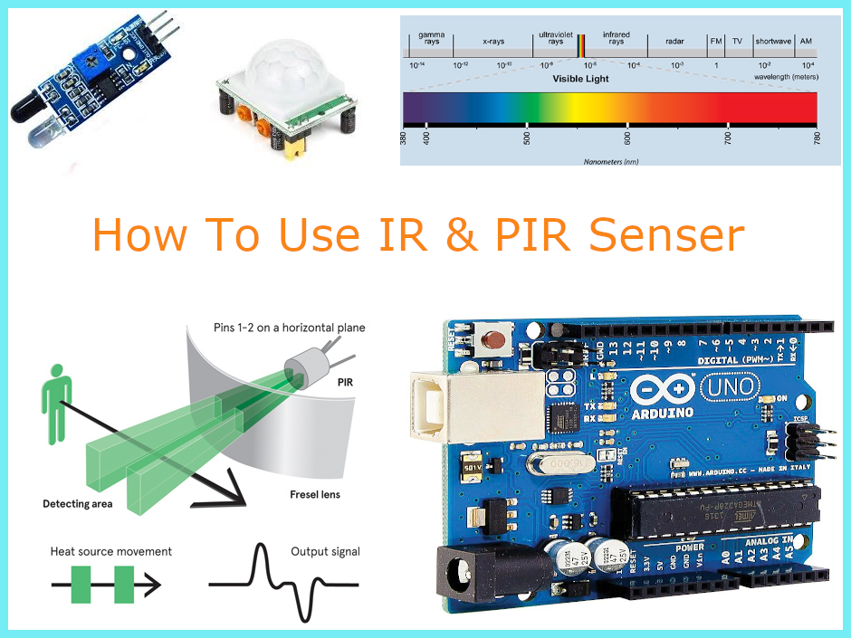
IR (Infrared) And PIR Motion Sensor With Arduino And With Raspberry PI
In this blog, we discuss the types of infrared sensors and interfacing of IR sensor with Raspberry Pi 4 and Arduino board.
Hello, in our previous section we discussed the interfacing of an ultrasonic sensor with Raspberry Pi and I hope you enjoyed the section. In this blog, we are going to discuss the types of infrared sensors and interfacing of IR sensor with Raspberry Pi 4 and Arduino board.
IR sensors are widely used in line follower robots and in 3D printing machines as IR limit switches. But do you know how IR sensor works? No! Don’t worry I’m here to tell you. Well, the IR sensor emits signals and it detects the object based on the state of the received signal. Talking more about infrared sensors, infrared sensors are of two types and they are as follows:
Types Of Infrared Sensors
1) Active IR sensor
2) Passive IR sensor
Active IR Sensor
The active sensor consists of a receiver and a transmitter, the transmitter is nothing but an IR LED or a simple LED source that produces light and, on the other hand, the receiver receives the signals transmitted by the IR transmitter.
Interfacing of The Active Sensor With The Arduino And Raspberry PI
Things You will Need
In the picture below, you can see a PCB and some components mounted on that PCB. That PCB is nothing but an IR sensor.
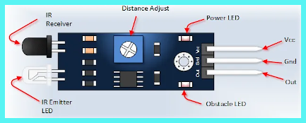
Up to this point, what we read was about the basics of all IR sensors, in this part of this blog we will be discussing the interfacing of IR sensors with Arduino and with Raspberry Pi; as you can see in the following image, the module has three output pins GND, VCC and signal. Out of which GND and VCC are explicitly used to power the module and we get output at the signal pin.
So, to get the output from the sensor, you have to power the module through an Arduino or Raspberry Pi board and get the output on its output pin. You may be thinking this and yes, it is somewhat correct but there is a catch, what would you do if the sensor would not output accurately??
How Can We Tell That The IR Sensor Is Working or Not?
There could many reasons for not getting the correct output from the sensor and a few of them I have listed below.
Program Issue
Yes! I know that you do not make such mistakes, but if the module is not working, then checking such small things can also help. So please try to check if you have connected the signal pin to the correct pin.
Output Gain of 555 Timer IC is Not Adjusted Properly
This is the most commonly encountered issue; Such issues are aggravated by improper adjustment of the gain of the 555 timer IC and this problem can be resolved by adjusting the potentiometer mounted on the module to its correct position.
Sort-Circuit In PIR Sensor
I don’t think I need to explain this, you are smart enough to understand the reason for such issues. Any part of the module is overheating it means that the module is damaged and cannot be used further.
IR Sensor is Still Not Working
– If an onboard part is not heating, take out your phone and turn on the camera on this module, if you see a red light from the sensor, you can tell that the module is fully functioning and all connections need to be rechecked.
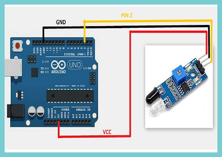
IR Sensor Interfacing With Arduino Board
The following sketch shows the interface of the IR sensor with the Arduino Board. In this sketch, we have connected the module’s signal pin to the Arduino’s D7 and powered this module through the VCC and GND pins.
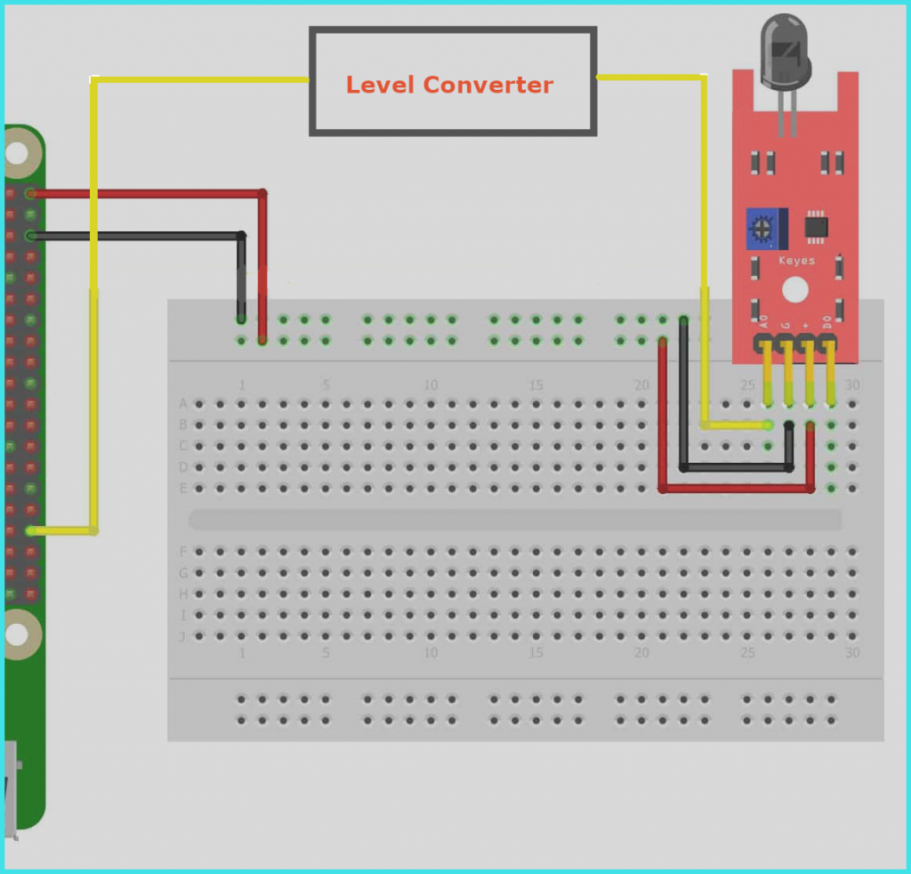
IR Sensor Interfacing With The Raspberry Pi
The following diagram shows the interfacing of the IR sensor with the raspberry pi. In this diagram, we are powering the IR sensor through the Raspberry Pi and we are using a level converter between the sensor and the Raspberry board, we are using the level-converter because the Raspberry cannot handle voltage higher than 3.3v on its GPIO pin. And if we do not use the level converter then there is a high risk of damaging the Raspberry Pi board due to the high voltage. so I would recommend using the level converter.
IR Sensor Python Code For Raspberry Pi
import RPi.GPIO as GPIO # Import Raspberry Pi GPIO library

def button_callback(Detection):

print("Object Is detected")

GPIO.setwarnings(False) # Ignore warning for now

GPIO.setmode(GPIO.BOARD) # Use physical pin numbering

GPIO.setup(34, GPIO.IN, pull_up_down=GPIO.PUD_DOWN) # Set pin 10 to be an input pin and set initial value to be pulled low (off)

GPIO.add_event_detect(10,GPIO.RISING,Detection=Object_detected) # Setup event on pin 10 rising edge

GPIO.cleanup()
PIR Sensor Motion Introduction
Unlike an active infrared sensor, passive IR sensors do not require a separate transmitter and a receiver. Such IR sensors capture the ambient heat and detect the object based on a deflection in the reading.
These sensors mainly used in home surveillance applications.
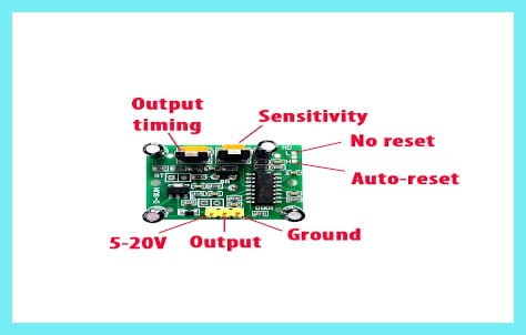
Apart from all these basics, if you check the module, you will see two potentiometers on the PIR sensor.
A potentiometer designated as sensitivity used to adjust the sensing the range. And a potentiometer designated as Output-timing used to adjust the delay.
Troubleshoot if the PIR module still doesn’t work
There can be many reason in which the module may stop working and a few of them I have listed below.
The Module is Not Giving Any Output in The first Minute After Turning it on
If you are having this problem, don’t worry, it is not a problem, in the first minute after the power is applied, the PIR sensor starts reading the IR rays around it. Therefore, let it be stable in the surrounding environment.
The output is not stable
If you are experiencing this problem, there are two reasons, first, that you have mistakenly changed the first potentiometer (sensitivity) of the module to its maximum position and the second cause of the problem may be the incorrect positioning of the PIR sensor. If you have installed the PIR sensor at a point where the PIR sensor comes in direct contact with air and light. This could then be the reason that the sensor is producing the wrong output.
Interfacing PIR sensor with Arduino
The following fig. Shows the PIR sensor’s interface with the Arduino board. In this, we connected the signal pin of the PIR sensor to the D9 pin of the Arduino board and powering the sensor through the Arduino itself.