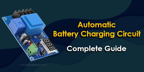
Automatic Battery Charging Circuit – Complete Guide
Mostly, all of the battery chargers use the automatic battery charging circuit to perform the charging operation smoothly and maintain the battery life.

Do you believe that battery chargers became an important part of our everyday lives, in both private and professional manner?
The fact that we want to use portable electronic equipment which needs a battery to operate. Similarly, in the market, there are varieties of battery-operated electronic equipment available like Mobiles, Electric Bicycles, Laptop, etc.
Most of us are not engineers but want to be able to fix and prevent battery issues in a simple way. To solve such issues, we use the battery charger. It is safe for all users to operate. Also, it is safe to travel from one place to another (via road) so that anyone can use it with flexibility.
The geeky people are always curious about the functioning of the battery chargers. In this blog, we are going to discuss the Automatic Battery Charging Circuit and its parameters.
Fundamental Charging Parameters
There are three fundamental parameters that need to be considered while charging the battery safely:
- Constant Current (CC)
- Constant Voltage (CV) and
- Auto Cut-off
Constant Current – Here, the amount of battery charging current is fixed. This current is maintained by varying the voltage.
Constant Voltage – Here, the current will be varied as per the battery charging requirement while keeping the voltage constant.
Auto Cut-off – It continuously detects battery charging voltage and once the battery reaches the full charge level, cuts off the charging voltage.
These three are the basic fundamental things that need to charge the battery successfully without affecting battery life.
In lithium-ion batteries, apart from these parameters, thermal management and step charging is also important to maintain the battery voltage and its life. Li-ion battery uses the BMS (Battery Management system) to maintain these parameters.
Let’s figure out the above fundamental parameters in brief.
Why CC and CV important?
The charging current rate is the most important factor which significantly influences the behaviour of the battery. It is a simple method that uses a small constant current to charge the battery during the complete charging process. When the battery reaches its predefined value, CC charging stops.
Mostly, this method is used for charging NiCd, NiMH and Li-ion batteries. A high charging current charges the battery fast but significantly affects the battery life. Therefore, a low charging current provides high capacity utilization but charge the battery slowly which is inconvenient for EV applications.
For example, in the 2S lithium-ion battery pack, two 18650 cells of 3.7V each are connected in series, so the total voltage is 7.4V. This battery pack should be charged when the voltage goes down to 6.4V (3.2V per cell) and charging should be completed up to 8.4V (4.2V per cell). Hence 6.4V and 8.4V values are already fixed for this battery pack.
Another method is constant voltage charging which maintains the predefined voltage to charge the battery. If the voltage is constant, the charging current decreases as the battery charges.
The battery charging requires a higher current value to provide a constant voltage at an early stage. A high charging current from 15 % to 80% provides fast charging, but it stresses the battery and can affect the battery life.
Suppose, we have decided a value of 1000mA as Constant Charging current. So initially when the battery charging starts, the charger should get into CC mode and push 1000mA into the battery by varying the charging voltage. Due to this, the battery will charge and voltage will start to increase slowly.
Constant Voltage Circuit
Here, we consider the CV mode of lithium battery charger in which we have to regulate the battery voltage from 6.4V to 8.4V as discussed earlier. The voltage regulator IC LM317 can do this by using just two resistors. The below circuit describes the battery charger circuit with constant Voltage mode.

To calculate the output voltage for the LM317 Regulator,
- Vout= 1.25*(1= (R2/R1)) where, 1.25 is the reference voltage.
Here, the output voltage (Vout) should be 8.4V. To build this circuitry, the value of R1 should be less than 1000 ohms so we use a 560 Ohms Resistor. With the help of the above formula, we can calculate the value of R2.
- 8.4V= 1.25*(1+(R2/560ohm)
- R2= 3.3KOhm.
Constant Current Circuit
Using a single resistor, the LM317 IC can be a current regulator. The below diagram shows the battery charger circuit for this current regulator.

Auto Cut-off Circuit
The auto cut off is the most important parameter of the battery charging. Nowadays, most of the batteries use the auto cut-off circuit. The below circuit diagram shows the battery charger circuit with the auto cut-off feature. It is implemented by using the adjustable voltage regulator LM317.
This circuit will give adjustable DC supply output voltage and charges the battery. The LM317 is a monolithic Integrated IC that is available with three different packages. This adjustable voltage regulator delivers a 1.5A load current and provides an output voltage range from 1.2 to 37 V.
Working of Auto Cut-off Circuit

Basically, it uses basic power supply components like transformer, rectifier, filter and regulator. The Stepdown Transformer (230V to 15V) step down the AC power supply. Next, the rectifier uses four 1N4007 diodes which convert step down AC into DC.
Capacitor C1 and C2 are used for filter operation. To regulate the voltage, we have used C1 LM317 IC. It also works as a current controlling device.
Here, the variable resistor VR1 changes the supply to the ADJ (Adjust) pin of the voltage regulator and hence it changes the output voltage.
Here, we have shown the green and red LED. The green LED shows the Charging condition of the battery and the red LED represents the complete charge of the battery.
When the battery becomes complete charge, the Zener diode (12V) generates the reverse voltage which flows to the base of the BD139 transistor and turns it ON. Due to this conduction in a transistor, the ADJ pin of the voltage regulator will connect to the ground which cuts-off the output voltage from the regulator. During this continuous process, to avoid the thermal Runway, use a heat sink with a voltage regulator.
IC LM317 provides a variable output voltage. This voltage can be varied with the help of an ADJ pin so the total output voltage is as,
- Vout = Vref (1 + R2/R1) + IADJ R2
Where Vout is the output voltage.
According to the resistor position, the formula will be,
- Vout = VREF (1 + VR1 / R1) + I ADJ VR1
Supplying Current depending upon Battery Rating
It is very important to decide the charging current to maintain the battery life. This charging current depends upon the capacity of the battery (ampere-hour rating). Every battery has a specified ampere-hour rating. This is the charge storage of the battery.
Kindly refer to the below sample calculations for charging time. The below calculations are approximate. The charging current is not the same at all the time. As the battery reaches near to full charge, the charging current decreases.
For Example, we have a battery with a capacity of 50 Ah:
First, we will calculate the charging current. As per the standard, the charging current should be 10% of the battery capacity.
Therefore, charging current for 50A Battery = 50 Ah x (10/100) = 5 Amperes.
But due to some losses, we may take 5-8 Amperes for battery charging purpose.
Suppose we considered 8 Amp for charging purpose,
Then, the charging time for 50Ah battery = 50 / 8 = 6.25 Hrs.
But this is an ideal case, practically, it has been noted that 40% of losses occur in the case of battery charging.
- 50 x (40 / 100) = 20 …..(120Ah x 40% of losses)
Therefore, 50 + 20 = 70 Ah ( 50 Ah + Losses)
Battery charging time = Ah / Charging Current
- 70 / 8 = 8.75 Hrs ( in real case)
Therefore, a 50 Ah battery would take around 9 Hrs to fully charge in case of the required 8A charging current.
If your battery has a capacity of 50 Ampere-hour, then you should not use a charger with a charge current of 5A. If so, then it will take around 10 hours to charge the battery and definitely, you won’t like this.
An ideal charging time for batteries should be 2-3 hours. This charging current rate can vary with the types of batteries so you can set the charging current as per the battery capacity and its type.
Final Words
I hope this article helps you to understand the complete guide of an automatic battery charger circuit. The battery chargers are varied with the applications like a mobile phone charger, electric vehicle battery chargers and charge stations. As per the battery specification, we can design the battery charger circuit using SCR, Op-Amp, different regulator ICs etc.


