


-42%


Automatic Pump ON/OFF Base on Fire DIY Experiments Science Project Model STEM KIT (Assembled), 100% Tested
Original price was: ₹1,025.00.₹599.00Current price is: ₹599.00. + GST

Touch Switch With Lamp DIY Experiments Science Project Model STEM KIT (Assembled), 100% Tested
Original price was: ₹1,025.00.₹599.00Current price is: ₹599.00. + GST
Theft Alarm Using IR Sensor DIY Experimentsl Science Project Model STEM KIT (Assembled), 100% Tested
Original price was: ₹1,025.00.₹599.00Current price is: ₹599.00. + GST
-
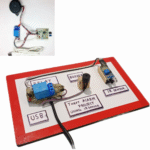
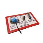
- Theft Alarm Using IR Sensor – Fully assembled, 100% tested kits.
- Includes full documentation with circuit diagrams, PCB layout, and testing documents.
- YouTube videos available for easy understanding.
- https://youtu.be/PM22ugMH5qg?si=NnmEJLpu6STxz4do
- 100% support available on working days from 11 AM to 6 PM via email (smartxbrains@gmail.com).
- Fastest delivery across India. Ideal for electronics projects, this Theft Alarm Using IR Sensor STEM Kit ensures reliability and performance.
97 in stock
Description
Please Note we are only providing kit we marked as ACTUAL PRODUCT, project shown customer needs to do at there own we just provide reference.
Abstract:
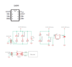
The Theft Alarm using IR Sensor circuit is built using a readily available IR sensor, comparator IC LM393, and a relay. The photo diode detects light intensity, while the LM393 comparator processes the signal. When IR beam interruption occurs, the photo diode stops conducting, triggering the alarm. The circuit design minimizes cost and complexity, using common components for reliable operation.
Application of the Circuit:
This Theft Alarm system is designed to detect interruptions in an IR beam, activating an alarm in its absence. Unlike other IR-based circuits, this design uses a simpler and more cost-effective setup, making it ideal for various electronics and automation projects.
Why this Particular Circuit:
The IR sensor and photo diode system ensure easy beam interruption for detection. The circuit operates on a 5V DC supply, which is commonly available, enhancing its usability for various DIY and educational projects.
Explained Working of Circuit:
The Theft Alarm works by detecting IR beam interruptions with a photo diode. The LM393 comparator processes the input from the photo diode, triggering the relay. In the absence of the IR beam, the relay opens, and the alarm sounds. When the beam is present, the system stays inactive.
How to Build:
Carefully read the manual, study the circuit diagram, and assemble the components on the PCB. Resistors and capacitors are identified through color coding and numerical values. Sockets for ICs, rather than the ICs themselves, are soldered to simplify troubleshooting.
Testing the Kit:
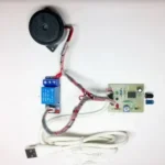
After assembling the components, connect a 5V DC power source. Hold a hand over the IR sensor to test—when the beam is interrupted, the alarm sounds. Adjust the resistive value of R2 to set the desired detection sensitivity.
ICs Used:
The LM393 comparator IC is the only IC in this circuit. It’s a popular and commonly used 8-pin differential comparator.
Part List:
- Semiconductors: LM393 (IC U1 – 8-pin)
- Resistors: R1 – 100 Ohm, R2 – 10k Ohm (variable), R3 – 1k Ohm, R4 – 1k Ohm, R5 – 10k Ohm, R6 – 10k Ohm
- Capacitors: C1 – 1uF
- Miscellaneous: IR sensor (D4), Photo diode (D3), Red LED (D1), Green LED (D2), 5V USB cable, Buzzer, Relay, PCB.
Key Applications:
Ideal for electronics projects, automation, robotics, and educational purposes. Optimized for performance in India-specific environments.
Keywords:
- Theft Alarm Using IR Sensor DIY STEM Kit
- 100% Tested
- electronic components India
- buy Theft Alarm Kit online
- Theft Alarm DIY experiment kit
- high-quality STEM kits
- Theft Alarm system India.
Reviews (19)
You must be logged in to post a review.
Shipping and Delivery
Related products

Automatic Temperature Control Fan DIY Experiments Science Project Model STEM KIT (Assembled) – 100% Tested
-
- Automatic Temperature Control Fan complete assembled kit – 100% tested.
- Includes full documentation: circuit diagrams, PCB layout, and testing documents.
- YouTube videos available for easy understanding.
- https://www.youtube.com/watch?v=3-Kn_HD-W4I
- 100% support available on working days (11 AM - 6 PM). Email us: Smartxbrains@gmail.com.
- Fastest delivery across India. Ideal for electronics projects, automation, and educational uses, this kit ensures reliability and performance.


Automatic over temp detection and alert Ready DIY Experiments Science Project Model STEM KIT (Assembled), 100% Tested
- Automatic Over Temp Detection and Alert – Complete assembled kit, 100% tested.
- Full documentation, including circuit diagrams, PCB layout, and testing guide.
- YouTube videos available for easy assembly instructions.
- https://youtu.be/07QBYB69fVU?si=UAtohVuQwSKT3sJf
- 100% support on working days (11 AM - 6 PM). Email: smartxbrains@gmail.com.
- Fastest delivery across India. Ideal for electronics projects, automation, and STEM education.
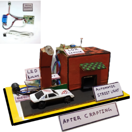

LDR & Relay-Based Street Light Controlling DIY STEM KIT Science Project Model (Assembled), 100% Tested
- LDR & Relay-based Street Light Controlling – Complete assembled kit, 100% tested.
- Includes full documentation: Circuit diagrams, PCB layout, and testing documents.
- YouTube videos available for easy understanding.
- https://www.youtube.com/watch?v=2Avy6w8KXbY
- 100% support on working days (11 AM - 6 PM), email: Smartxbrains@gmail.com.
- Fastest delivery across India. Perfect for electronics projects and automation needs.

Touch Switch DIY Experiments Science Project Model STEM KIT (Assembled), 100% Tested
-
- Complete Touch Switch DIY Science STEM Kit – 100% Tested and ready to use.
- Includes full documentation: circuit diagrams, PCB layout, and testing details.
- Step-by-step video tutorials available on YouTube for better understanding.
- https://youtu.be/wgNBk1AAEa0?si=_03gIQmEBCwzM_8F
- Dedicated support on working days (11 AM - 6 PM) via Smartxbrains@gmail.com.
- Fastest delivery across India – ideal for electronics projects, automation, and STEM learning.

Transformer Vibration Detection DIY Experiments Science Project Model STEM KIT (Assembled), 100% Tested
- Transformer Vibration Detection DIY KIT – Assembled and 100% tested.
- Full documentation, including circuit diagrams, PCB layout, and testing documents.
- Includes YouTube videos for easy understanding.
- 100% support on working days from 11 AM - 6 PM via email: Smartxbrains@gmail.com.
- Fastest delivery all over India. Perfect for electronics projects in India, ensuring reliability and performance.

LED Lighting in Aquarium using LDR Sensor Ready DIY Experiments Science Project Model STEM KIT (Assembled), 100% Tested
- LED Lighting in Aquarium STEM Kit uses an LDR sensor for light automation (Assembled & 100% Tested).
- Complete documentation: Circuit diagrams, PCB layouts, and testing documents included.
- Learn through detailed YouTube tutorials.
- https://www.youtube.com/watch?v=2Avy6w8KXbY
- Full customer support on working days (11 AM–6 PM) via email at Smartxbrains@gmail.com.
- Fast delivery across India for DIY science and automation projects.
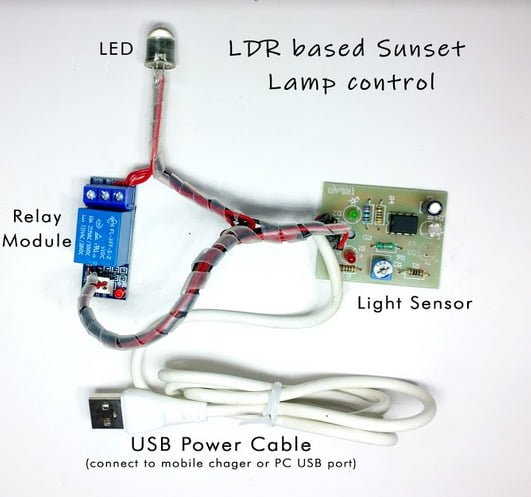
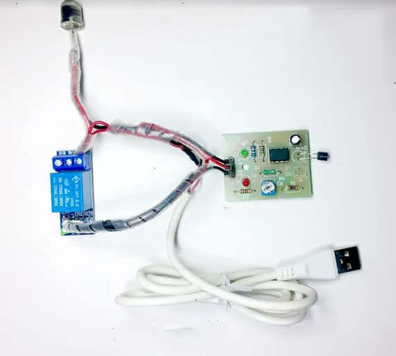
LDR based Sunset Lamp control Ready DIY Experiments Science Project Model STEM KIT (Assembled), 100% Tested
LDR-Based Sunset Lamp Control STEM Kit (Assembled, 100% Tested) – Ready DIY Science Experiments
Short Description
- Complete LDR-based Sunset Lamp Control Kit, pre-assembled and 100% tested for reliability.
- Includes detailed documentation with circuit diagrams, PCB layout, and testing instructions.
- Watch easy-to-follow assembly and usage videos on YouTube.
- https://www.youtube.com/watch?v=2Avy6w8KXbY
- Get expert support on working days (11 AM - 6 PM) via email at Smartxbrains@gmail.com.
- Fastest delivery across India. Perfect for educational projects and electronics enthusiasts.

Heat Sensor Using NTC DIY Experiments Science Project Model STEM KIT (Assembled), 100% Tested
- Heat Sensor Using NTC, Complete assembled kit, 100% tested.
- Full documentation includes circuit diagrams, PCB layout, testing documents, etc.
- Videos available on YouTube for easy understanding.
- https://www.youtube.com/watch?v=07QBYB69fVU
- 100% Support on working days 11 AM - 6 PM, Email us at Smartxbrains@gmail.com.
- Fastest delivery all over India. Perfect for electronics, automation, and educational projects in India. Heat Sensor Using NTC DIY Experiments Science STEM KIT (Assembled), 100% tested ensures reliability and performance.
19 reviews for Theft Alarm Using IR Sensor DIY Experimentsl Science Project Model STEM KIT (Assembled), 100% Tested
There are no reviews yet.