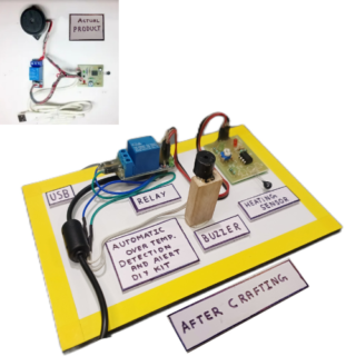
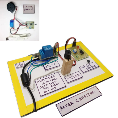
Fire Detection Alarm System DIY Experiments Science Project Model STEM KIT (Assembled), 100% Tested
Original price was: ₹1,025.00.₹599.00Current price is: ₹599.00. + GST
-
- Fire Detection Alarm System assembled kit, 100% Tested.
- Full documentation, including circuit diagrams, PCB layout, and testing documents.
- Videos available on YouTube for easy understanding.
- https://youtu.be/v3xl6-t9OYA?si=-fnPKeqq45WF4vkr
- 100% support on working days from 11 AM – 6 PM. Email: Smartxbrains@gmail.com.
- Fastest delivery all over India. Perfect for electronics projects, automation, and educational uses, ensuring reliability and performance.
98 in stock

98 in stock
99 in stock
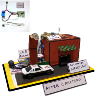
Please Note we are only providing kit we marked as ACTUAL PRODUCT, project shown customer needs to do at there own we just provide reference.
Abstract:
The Fire Detection Alarm System circuit presented here uses a Flame Sensor, comparator IC LM393, and a relay. The Flame Sensor detects fire intensity, while the LM393 IC functions as a comparator. In the absence of fire, the flame sensor stops conducting, and the buzzer stays off. When fire is detected, the flame sensor starts conducting, activating the buzzer.
Application of the Circuit:
Most flame sensor-based circuits on the market require costly components and complicated circuitry. This circuit uses readily available flame sensors, reducing cost and complexity. The Fire Detection Alarm System circuit activates a buzzer upon detecting fire, providing continuous feedback.
Why This Particular Circuit:
The circuit operates on 5V DC and uses a Flame Sensor as the fire detector, making it cost-effective and reliable.
Explained Working of Circuit:
The IC LM393 is used as a comparator, processing the output from the flame sensor. In normal conditions, no fire is detected, and the buzzer stays off. When fire is detected, the buzzer activates. The relay serves as a switch to control the circuit’s operation.
How to Build:
Read the manual thoroughly and study the circuit and PCB layout provided. Solder the components according to the PCB layout. Use IC sockets for easy troubleshooting and replaceable ICs. Start soldering components from the left-most corner of the PCB, paying attention to component polarity.
Testing the Kit:
After assembling and soldering the components, connect a 5V external power source. Hold a heat source near the flame sensor to test. The buzzer should sound in response to the fire detection.
ICs Used:
The only IC used is LM393, a dual differential comparator commonly used in similar circuits.
Part List:
- Semiconductors:
- U1 – LM393 (8-pin IC)
- Resistors (all 5% carbon unless specified):
- R2 – 10k Ohm (variable)
- R3 – 1k Ohm
- R4 – 1k Ohm
- R5 – 10k Ohm
- R6 – 10k Ohm
- Capacitor:
- C1 – 1uF
- Miscellaneous:
- D4 – Flame Sensor
- D1 – Red LED
- D2 – Green LED
- 5V USB Cable
- Buzzer
- Relay
- PCB
Key Applications:
Used widely in electronic circuits, automation, robotics, and educational projects. Optimized for reliable performance in Indian environments.
Keywords:
- Fire Detection Alarm System DIY STEM KIT (Assembled)
- 100% Tested
- electronic components India
- Fire Alarm DIY Kit
- buy Fire Detection Alarm Kit
- Fire Alarm STEM Kit price
- Fire Alarm Sensor system


Lokesh (verified owner) –
Drone parts i ordered and found ok
Rahul (verified owner) –
Drone parts i ordered and found ok
Paaji (verified owner) –
Online best cost electronic components
Devendra (verified owner) –
Less cost than other websites
Rahul (verified owner) –
Online best cost electronic components
Vivek (verified owner) –
Very well worth the money.
Vivek (verified owner) –
Good support and recommended
Ketan (verified owner) –
Online best cost electronic components
Priya (verified owner) –
Drone parts i ordered and found ok
Rahul (verified owner) –
Very fast delivery.
Harsh (verified owner) –
I got my project done with these components Great Support
Rahul (verified owner) –
Good service.